A closer look at the Sensor Front-End
The probe combines pH, ORP and temperature sensors and groups these into 5 wires. We will start by looking at a few general things to know about these kinds of sensors. Knowing how a pH, ORP and T sensor actually works can help our reverse, as this gives us some clues as to what we are looking for.
Background Information on Pool Measurements
Background info: pH
The pH electrode is composed of a pH-sensitive glass membrane directly in contact with water at its tip (in the form of a bulb), enclosed in a container filled with a reference solution [1]. The tip of the glass bulb allows ion exchange with the water, which varies with the hydrogen ion concentration in the water (i.e. the pH). The reference solution surrounding the glass electrode has a pH of 7, which is in the middle of the 0-14 scale. By construction, a potential difference is formed in between the two electrodes, which is linearly proportional to the difference of pH between the reference solution and the measured solution. This means that in an ideal pH probe, the output voltage of the probe is 0mV at pH7.
The ideal probe is represented below in green. Non-ideal probes, by non-zero offset and different slope, are represented respectively in red and green.
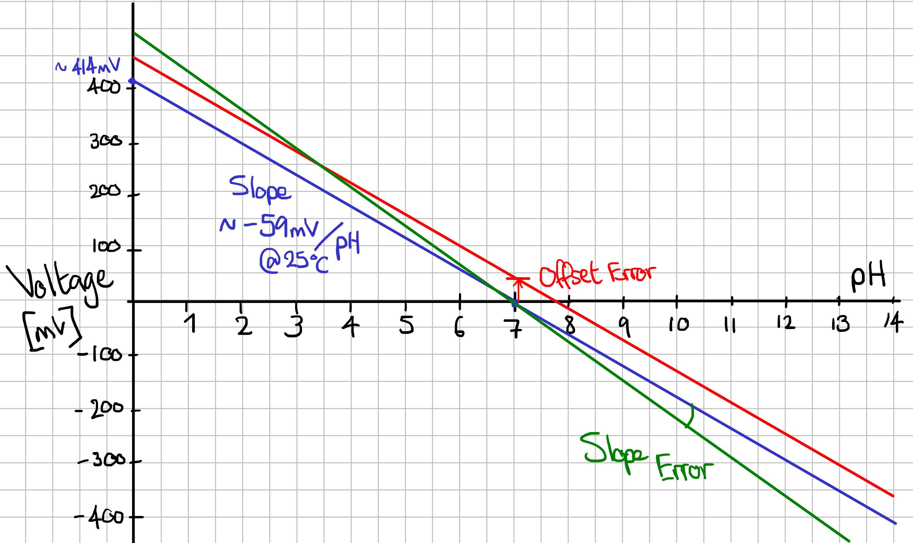
In the real world, the slope is not exactly -59.16mV/pH, and the offset at pH7 is not 0mV. It’s possible to compensate this by performing a 2-point calibration of the probe, to fix the 2 unknowns (Slope, Offset) and use these values to compensate the measured value. We don’t know if pHin has calibrated their probes, and whether the calibration information is stored in the cloud or in the probe itself. Given that it’s impossible to communicate with the probe (it is non-connectable over BLE), and given that the probe should ideally be re-calibrated periodically, it’s likely that any calibration information is in the Hayward cloud, and so is not accessible to us. And yet, the pHin team recently announced that there were working on a view-only application, which would make it impossible to retrieve calibration information from the cloud. If the calibration is not stored inside the probe, it would mean that measurements that do not go through the Hayways cloud are uncalibrated.
Note that the pH/mV slope also depends on the temperature. In high-quality probes, the temperature measurement can be used to compensate the pH slope. Again, we don’t know if pHin applied this kind of compensation. For practical purposes, it wouldn’t make a lot of sense to put of lot of effort into that because pool water is rarely far away from 25°C (but it could be noticeable in a hot tub).
Let’s summarize the pH background info with practical details for the electronics design:
The pH probe has is a bipolar output ranging from -500 mV to +500mV
By construction, the impedance of the electrode is extremely high: from 10 MOhm to 100 MOhm!
The measurement can be improved with prior knowledge of slope and offset at 25°C, and further information on the temperature dependency.
This impacts the electronics design in 2 ways:
To work with a single-ended front-end (i.e. powered off VDD referenced to ground), we need to apply an offset voltage to the probe.
To be able to work with the extremely high impedance of the pH probe, it needs to be connected to a high-input-impedance component and the entire path of the high-impedance track must be protected from external interfence.
Background info: ORP
Swimming pool sanitation aims to remove micro-organisms and organic matter from the water, which may be sources of pathogens and a vector for disease propagation between swimmers. The chemical-based strategies like chlorine rely on a chemical reaction known as Oxidation, in which an oxidizing agent interacts with other molecules by accepting electron transfer from the other molecule. When taking electrons from micro-organisms, oxidizing agents break down the inner structure of the organisms’s cells. We speak of disinfection. In a similar fashion, oxidation breaks down non-living organic matter in the swimming pool. Sometimes the distinction is made between disinfection and oxidation, because breaking down non-living organic matter, although important to reduce the development of micro-organisms, can be seen as a reaction that consumes chlorine in parallel to the disinfection reaction. Any organic matter than is removed by other means, like filtering, will reduce the demand for the available oxidizing agent.
When Dichlorine \(Cl2\) is added to a solution, it interacts with water using the following reaction:
This reaction is always very fast, so pure Cl2 stays only briefly in its original form. \(HOCl\), or Hypochlorous acid, is a product of this initial reaction, and is the main oxidation agent in this type of pool sanitation. Its concentration in the water depends on the following equilibrium (i.e. reversible) reaction:
Hypochlorous acid and \(OCl^-\), or Hypochlorite ion, are equimolar at 25°C, when the pH is 7.5. Their relative concentration is very sensitive to the pH, as can be seen in this rough sketch (not drawn to scale and values may be slightly off):
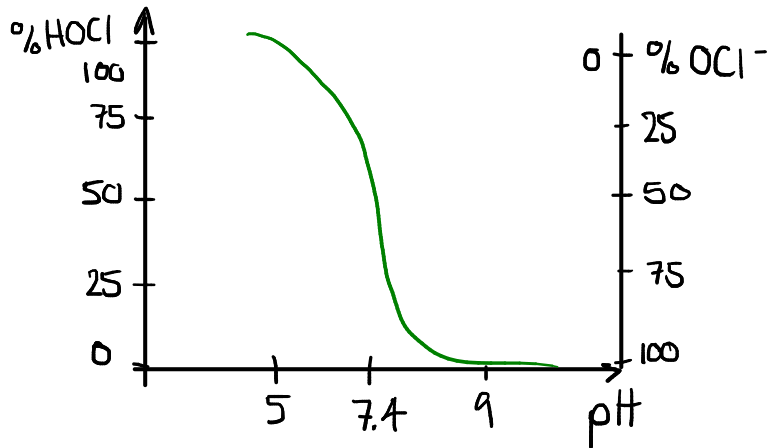
In pool water, since Hypochlorous acid is the main oxidation agent, we want to have a sufficient concentration of it at all times. The hypochlorite ion remains in the water as “available chlorine”, and converts gradually to \(HOCl\) as \(HOCl\) itself breaks down during the oxidation process. A well-balanced reaction (i.e. pH around 7.4) means that sufficient \(OCl^-\) will be converted to \(HOCl\), when available. If the pH is too low, there will be a high concentration of \(HOCl\), and since it is more volatile than \(OCl^-\) it will disspate faster. This results in a waste of chemicals. On the other hand, if the pH is too high, there will not be enough \(HOCl\) in the water, reducing the overall effectiveness of the sanitation.
As we can see from the above pool sanitation basics:
The pH is important and must be kept at the correct value.
The sanitation is garanteed by the availability of an oxidizing agent, brought into the water by the addition of chlorine.
An ORP probe measures the Redox (ORP is for Oxidation-Reduction Potential), which is proportional to the effectiveness of the main oxidation agent in the solution. In pool water, where \(HOCl\) is the main oxidizing agent, the measurement of ORP reflects directly the concentration of \(HOCl\).
In an ORP Probe, a reference wire is immerged in a KCl reference solution on one end, and another wire is immerged in silver chloride in the probe’s tip. The measured voltage at the ends of this voltaic cell is proportional to electron activity in the water. ORP is measured in millivolts and does not need to be converted to another scale.
Background info: Temperature
Measuring temperature can be done in a variety of ways: a very common approach is to use a thermistor, which presents itself as a temperature-dependent resistor. To perform a temperature reading, one can form a resistive divider between the thermistor and a resistor of a fixed, known value, in this manner:
Applying a voltage of known value at the input of this resistive divider will produce a voltage at the output which is dependent on the resistance of the thermistor, and so from that voltage it’s easy to recover the resistance of the RTD. Once the resistance is known, a simple formula can be used to recover the temperature.
Note
after reverse-engineering, I first interpreted the method used as a wheatstone bridge, then realized it is equivalent to a resistive divider with an extra leg in parallel to compute the exact value of the input voltage pin.
pH & ORP Front-End Schematics
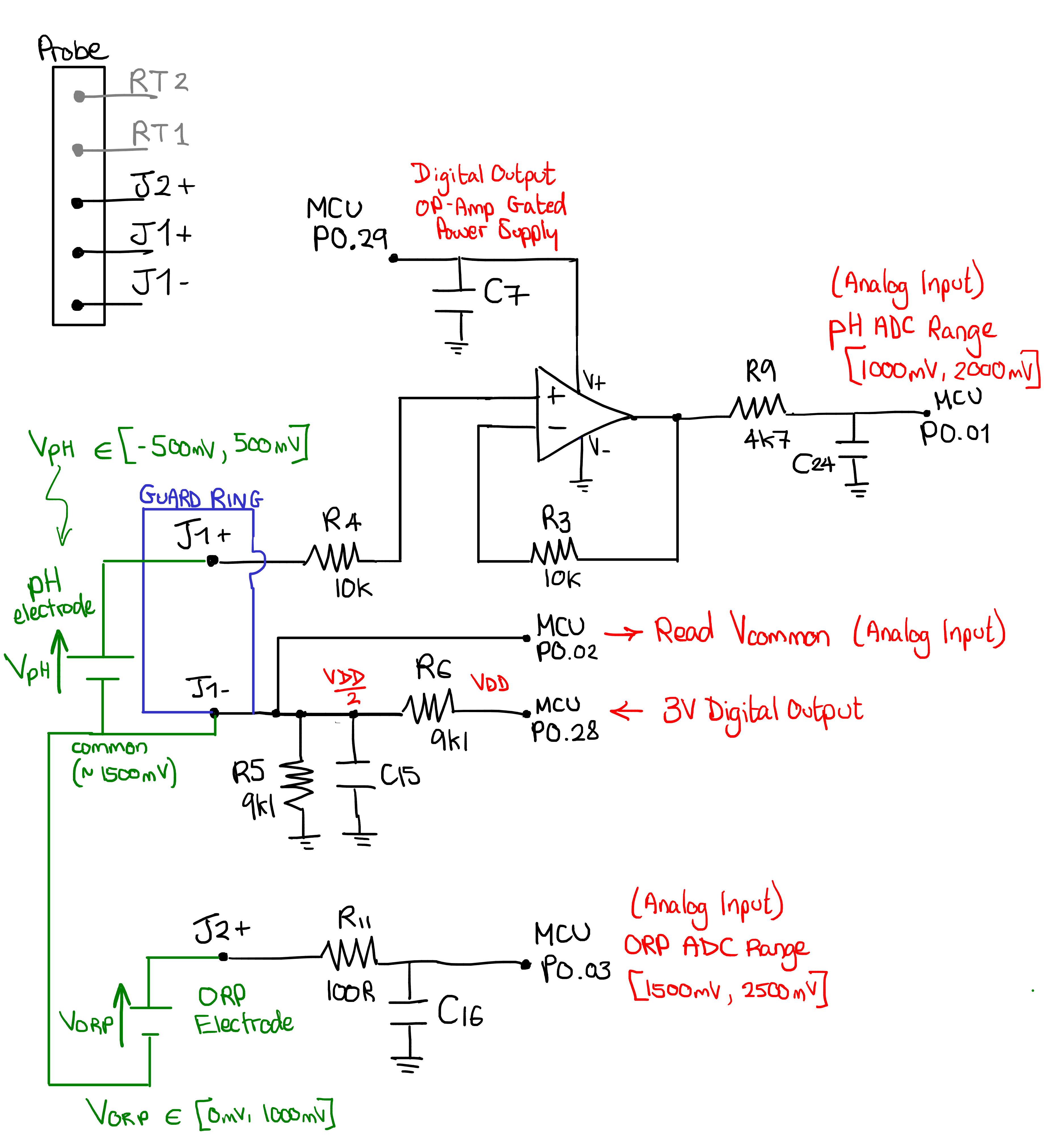
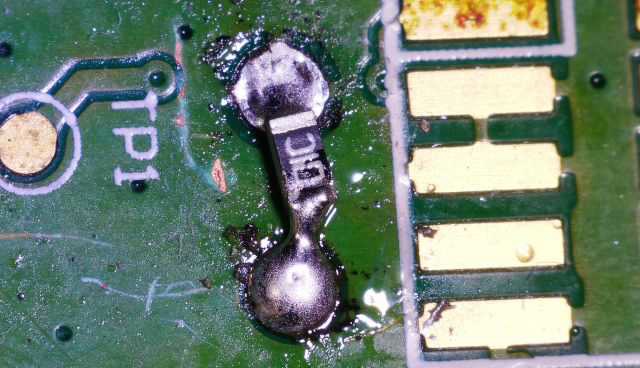
Now that we have covered some theory and deduced the pinout of the probe, let’s look at how pHin has designed their probe frontend. I started by testing continuity around the PCB, allowing me to recover the black parts of the following schematic. The other annotations were added later.
Note
we have already seen the role of the guard ring in Guard Ring
For the pH measurement, there is a dedicated op-amp of an unknown reference (the markings on the PCB are AHA and the package is a SOT-23, but the exact manufacturer and model is unknown). This amplifier is in a buffer configuration with a gain of 1. It’s sole (but critical) purpose is to offer a G-Ohm input impedance to the J1+ signal, which is the output of the pH probe (remember from the theory, the pH electrode has on the order of 100 MOhm output impedance). The characteristics of the buffer amplifier are selected with care: the most important parameter is to have a very low input bias current, as even the slightest current can product a significant voltage error when going through the high impedance of the pH probe. I would expect the maximum input bias current of this buffer to be somewhere around 1pA or less.
The op-amp is powered directly by a GPIO of the microcontroller (P0.29), which allows the microcontroller to completely turn off the amplifier outside of a measurement, saving energy. The R9/C24 low-pass filter cleans the signal. The output is connected to the microcontroller’s P0.1 pin, certainly configured internally as an analog input connected to an ADC channel.
For the ORP, J2+ is directly connected to the microcontroller’s P0.3 pin through a simple low-pass filter. I had a prior possible misconception that ORP probes had impedances of the order of 100k Ohm - 1M Ohm. If this is the case, I don’t expect the nRF51822 to offer a sufficiently high input impedance to not load the signal. I’m either wrong on the impedance of the ORP probe, or wrong on what the nRF51822 can handle (or right on both points, and the designers compensate the voltage drop, which seems a bit unconventional.)
The knowledge behind the rest of the annotations came gradually as I started analysing signals on an oscilloscope. To understand how a measurement is implemented, it’s useful to look at the following signals on a scope:
J1-
P0.28
P0.29 (Op-Amp Gated Power Supply)
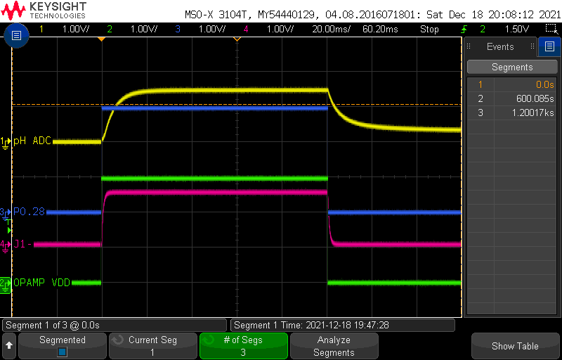
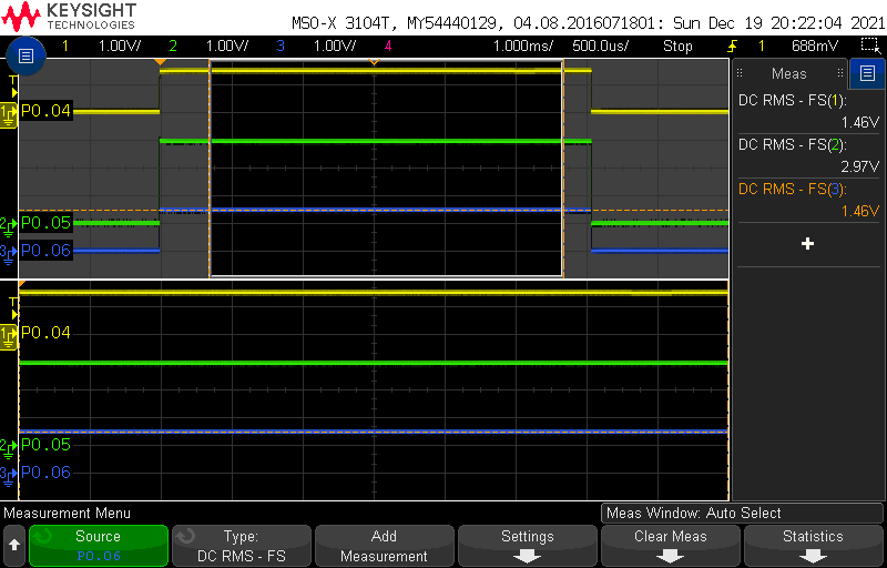
Here is a capture for a single sensor acquisition, which occurs every 10 minutes:
Let’s decode this together:
When the measurement is not running, all signals are at 0V. At the start of the measurement, pins P0.28 and P0.29 step up to the VDD voltage of the board (3V):
P0.29stepping up to 3V turns on the op-amp for the pH measurementP0.28stepping up to 3V applies a DC offset toJ1-(which rises slower due to the presence ofC15). The exact value of the DC offset onJ1-is fixed by the R6/R5 resistive divider, which have equal values, so the voltage ofJ1-is exactly half of VDD.
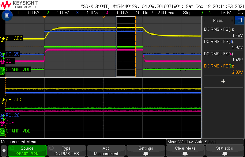
We can see here in more detail the exact timing of the ramp-ups:
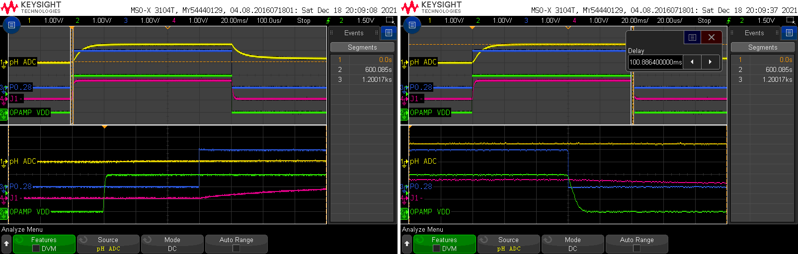
The op-amp power supply goes high first, followed 300 microseconds later by the P0.28 pin. At the end of the measurement, both P0.28 and P0.29 are set back to 0V.
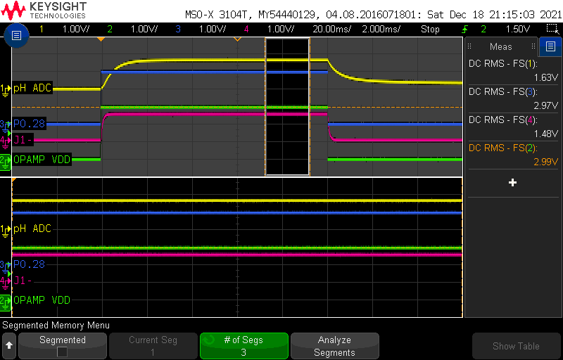
Looking at the signals over a window within the “ON” part of the measurement, we compute the following averages:
Op Amp Power Supply = 2.99V (~3V)
P0.28 = 2.97V (~3V)
J1- = 1.48V (~3V/2)
pH ADC = 1.46V
This was taken with the probe dipped in a pH7 buffer solution. If you didn’t skip the theory section above, you’ll remember that at pH 7, ideally, the pH electrode should have 0mV potential difference. So where does the 1.46V come from?
As we recall, the pH can vary between -500mV and +500mV. To avoid having to measure a bipolar voltage, the frontend applies a constant DC voltage to the “reference” side of the pH probe. This is what P0.28, R6/R5 and C15 are all about: they raise J1- by 1500mV with respect to GND, meaning that the output range of the pH probe goes from [-500mV, +500mV] to [1000mV, +2000mV], which is something that a single-ended ADC input can handle. The parts in green is my best guess of what is going on inside the probe itself. The J1- pin is the common reference for the J1+ and J2+ outputs, meaning that any offset applied to the common pin will also affect the ORP output. The ORP probe output range is thus translated from [0mV, +1000mV] to [1500mV, +2500mV].
Let’s go back to our pH measurement. At pH7, we expect a voltage difference of 0V across the pH electrode, so a value of 1500mV between the probe output and ground. 1.46V is close.
I repeated the above measurement using two other pH buffer solutions: pH4 and pH10.
In pH4, I get the following readings after a stabilization of more than 30 minutes:
In pH10, I get the following readings after a stabilization of more than 30 minutes:

pH buffer |
Expected Probe mV |
Expected ADC mV |
Real ADC mV |
Error mV |
|---|---|---|---|---|
4 |
177.48 |
1677.48 |
1630 |
47 |
7 |
0 |
1500 |
1460 |
40 |
10 |
-177.48 |
1322.52 |
1300 |
22 |
This may seem OK, but a 40mV difference is actually quite high. Remember that the sensitivity of the pH probe is -59mV/pH! The error isn’t constant, suggesting that there is a combination of offset and slope error.
To reduce the error, it’s important to measure the real voltage of the offset applied to J1-. This is the role of P0.2, which I have not mentionned yet. If P0.2 is connected to an ADC through an analog input pin, the real offset can be obtained and subtracted from the voltage measurement at P0.1, to retrieve the probe voltage. If we apply this compensation on our 3 measurements, we obtain closer values:
Compensated pH4 = 1630mV - 1480mV = 180mV (ideal = 177mV)
Compensated pH7 = 1460mV - 1480mV = -20mV (ideal = 0mV)
Compensated pH10 = 1300mV - 1480mV = -180mV (ideal = -177mV)
The errors are much smaller.
Note
The above compensation is equivalent to performing a differential measurement on the microcontroller’s ADC, between pins P0.1 and P0.2 for the pH, and pins P0.3 and P0.2 for the ORP.
Note
A scope not being the ideal tool to make precise voltage measurements is another factor contributing to the errors in this experiment. Also, let’s remember that we’re working on a device that is already beyond its intended battery life, and so the pH probe has non-negligeable mileage. Finally, and most importantly, when I was done with all these measurements I realized that one of the capacitors on the board was completely fried, leaking a lot of current and lowering VDD. If I had more time I’d redo these measurement to get nice data, but it would not change any of my conclusions.
This experiment helps us to gain an understanding of the frontend and insight on how we can stimulate the signals to emulate a wide range of input values. The purpose of that will be to finely control the values of pH, ORP and temperature, giving us reliable ground truth when attempting to reverse-engineer the encoding of the measurements in the BLE Advertisements.
Temperature Front-End Schematics
The temperature sensor is a thermistor, which is a component that has a temperature-dependant resistance. Thermistors can be modeled by the Steinhart-Hart Equation, but can also be characterised by the simpler Beta Parameter Equation, which is a partical case of the Steinhard-Hart Equation. The
\(\beta\) is an intrinsic parameter of the thermistor. We don’t yet know the Beta parameter of the pHin NTC.
\(R_0\) is the resistance of the thermistor, at the reference temperature \(T_0\), which is usually 298.15K (25°C). These are also intrinsic parameters of the thermistor, provided in the datahsheet.
\(R\) is the resistance of the thermistor at a particular temperature, T.
If we want to be able to use the Beta equation, we need to:
Recover the intrinsic parameters of the thermistor ( \(\beta\), \(R_0\), \(T_0\))
Measure the resistance of the thermistor and convert it to a temperature by solving the above equation for T.
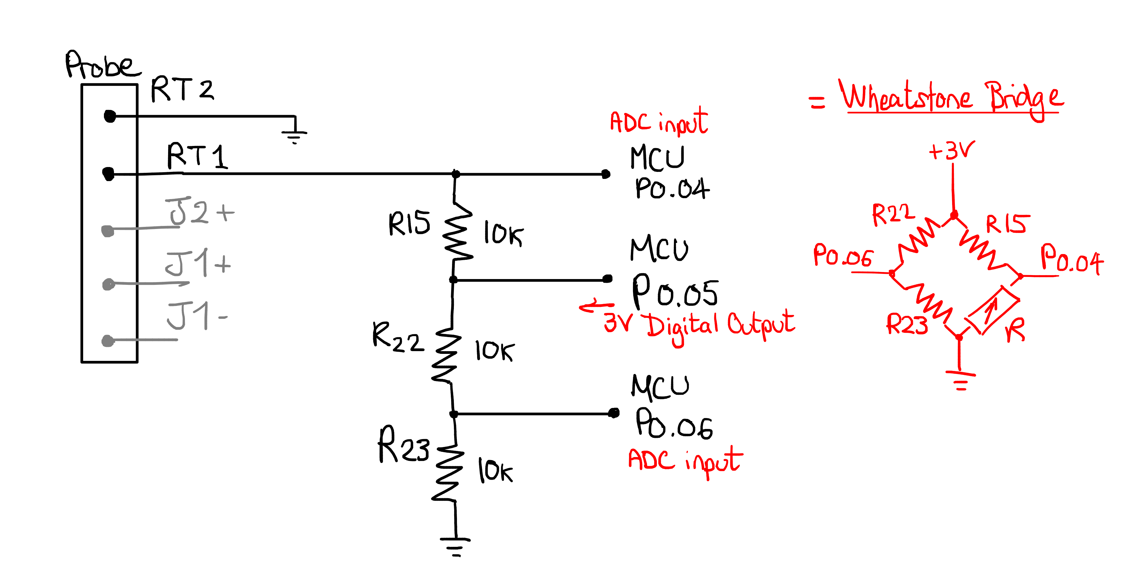
We will now study how the pHin measures the resistance of the thermistor. By analysing the PCB, we found the following layout.
Note
to measure the resistance of each resistor, these were unsoldered and measured individually.
The temperature is measured using a Wheatstone bridge.
Note
On hindsight: we don’t need to interpret this as a wheatstone bridge, it is just a resistive divider with an extra leg to recover the true voltage of the P0.05 pin. I didn’t update the rest of this section since it leads to the same result.
This is a widely used configuration used to measure an unknown resistor in an accurate way. You can read all about Wheatstone bridges on Wikipedia. This is a very basic form of a wheatstone bridge, because all 3 known resistors are of fixed value, meaning that the circuit does not attempt to adjust a certain resistor to have equal resistor ratios on each side of the bridge.
To solve for the unknown resistor in this simplified Wheatstone bridge, the microcontroller should proceed as follows
Set 3V on P0.05
Measure voltages on P0.04 and P0.06
Then, the unknown resistor can be recovered as follows.
When we apply 3V at the top of the bridge, the left and right halves of the bridge each for a resistive divider:
When all four resistors of the Wheatstone bridge are equal, \(V_{P0.04}\) and \(V_{P0.06}\) are the same. The bridge is said to be balanced, and seeing that we have three 10k resistors, we can be sure that the thermistor that was selected is 10k at 25°C. When the temperature is not 25°C, \(R\) is not 10k anymore and \(V_{P0.04}\) and \(V_{P0.06}\) are unequal. The difference between these voltages, which we call \(V_{64}\) can be expressed by combining the above equations:
To recover \(R\), one can use a lookup-table, or solve the above equation for R:
Now that we know a few things about the wheatstone bridge, we expect the microcontroller to apply VDD (3V) at P0.05, and measure the voltage using an ADC at P0.04 and P0.06.
To verify this experimentally, I unsoldered the thermistor probe terminals from the PCB, and replaced them with a fixed-value 0603 resistor across the pins:
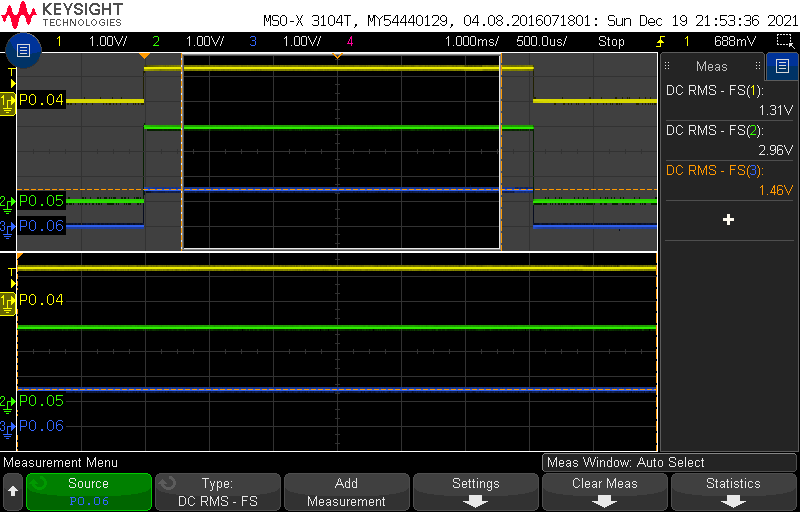
By replacing the resistor with a few different values, we can emulate the thermistor at known resistances. We start with 10k, the balanced bridge mode, and measure P0.04, P0.05 and P0.06 on a scope:
As expected, we have approximately 3V at P0.05, and 1.46V on either side of the wheatstone bridge.
Next, we will unbalance the bridge by replacing the resistor with an 8k2 value:
As we can see, the voltage of P0.04 has changed now that the thermistor is not a 10k anymore.
These measurements teach us everything we need to know about how the temperature is measured. When looking at the data to recover temperature, we will be looking for any other the following three types of data:
The voltages at the key points of the wheatstone bridge
A value in Ohms
The converted value in °K, °C or °F
If we obtain anything other than the converted value in °K, °C or °F, we will also need to use the thermistor’s Beta equation which depends on intrinsic parameters of the thermistor that we do not know yet (but that we can recover experimentally).